L1 Charging Pod: Verification
The simulations, integrated run and stress tests behind the design, with every finding from the independent reviews and how each was resolved.
Simulated and reviewed, not built. No pod has been built or tested. The models use representative part data. Results for the L1-Q and L1-W are on the L1 aircraft page; neither can use a pod as listed today. A licensed electrical engineer’s review and the bench and field tests listed in the design are required before anyone builds and flies it.
Simulation results
Revision 3 of this design rests on three checks, delivered in the release package (code, executed notebook, figures):
- seven simulations;
- three engineering analyses;
- a 165-check pass/fail suite (119 pod checks, 37 on-board solar checks and 9 L1 checks), including the integrated mission, the doc-to-code audit and the stress test below.
Two independent reviewers, each given only this document and the code, found 15 problems in revision 1 and 19 in revision 2, two of them critical each time. Each was reproduced, then fixed or stated as a limit; REVIEW.md in the package lists every finding and its fix. That a second review still found critical problems is the reason this design is not called finished. The analyses also covered areas revision 1 had not analysed: thermal, wind, snow, enclosure pressure, contact physics, tag visibility, drone mass, wiring, surge, emissions and storage life.
| # | Check | Finding | Status |
|---|---|---|---|
| 1 | PV string voltage, −40 to +45 °C | 150 V controller holds with 60- or 72-cell panels (95.6 / 109.0 V); a 100 V controller fails with 72-cell panels. Small-kit panels at Vmp 19 V stop charging near full at 45 °C | Small kit Vmp ≥ 20 V |
| 2 | CC/CV drone charge | Quad 1.08 h, VTOL 1.29 h from 25%. Steady-state ceiling 4.12 V per cell at +0.5% | 24.6 V only; full-charge mode removed |
| 3 | Energy balance | Solar charges per day confirmed (6.8 / 2.2 quad). Grid pods idled under the storage-only start rule | 80% grid credit; MPPT limit 25 A; cloud-edge transient ≤ 37 A for ≤ 2 s, within ratings |
| 4 | Sense check concept | A single-level check is fooled by water or debris films | Two-level check |
| 5 | Contact geometry | Five contacts lose about 21% of landings if one contact fails | Nine contacts on a 3 × 3 grid, 110 mm strips; tolerates two failed contacts and ±10 mm build error; ≥ 99.997% with σ = 100 mm scatter |
| 6 | Fault injection, 10 µs plant, 1 kHz firmware | Rev 1 relay had to break up to 125 A; a pad short with a working current limit went undetected. Rev 2 could power the pad after a drone left during WAIT, missed a conductor bridging the strips under a drone, and never simulated turn-on | MOSFET switch with hardware OV/OC (opens within 1 ms at every state of charge, alone if firmware fails); UV trip; WAIT exits on an empty pad; fresh sense check before power; 1 s sense re-check (≤ 0.2 kJ into any bridge); ramped turn-on; already-full refusal; full state machine implemented and tested |
| 7 | Sense circuit, component level, 1,200 builds | Rev 1 OV divider tolerance put the trip at 24.8–26.0 V; open pad could read inside the window; rectifier mode unmodelled. A 5S pack cannot be told apart by voltage | 0.1% dividers, 29.5 V boost, window 17.6–27.6 V: no false accept or reject in 490,800 cases. Per-cell drone BMS mandatory. Overvoltage trip moved to 25.05 V, band 24.89–25.21 V derived from tolerances and drift (rev 2's 25.30–25.50 V sat above 4.20 V per cell) |
| 8 | Case thermal | Sealed case with internal converter reaches 54 °C at 25 °C ambient. Pad surface reaches 50–65 °C. Leaving the solar controller inside gives 48 °C at 35 °C ambient | Heat-sink plate (0.25 K/W) carrying charger, solar controller and switch; white case; side shading: full rate to 34 °C ambient, reduced to about 40 °C, no charging above about 40 °C in full sun (confirmed by the integrated simulation). Pad temperature no longer gates charging |
| 9 | Wind, snow, pressure, contacts, magnetic field, wiring | Uplift exceeds weight at 18 m/s; sealed case sees 14 kPa; one contact can carry all 20 A; strip field is comparable to Earth's while charging; all wiring drops under 1% | 1.5 kN anchors (sized for all uplift on the windward pair); vent; 25 A contacts; no compass alignment until the charge ends |
| 10 | Tag visibility, drone mass, storage life | 120 mm tags leave view below 1.1 m on a 60° camera; kit costs 9–13% of range on a 3 kg drone; storage cycling gives 9–15 years at solar sites but about 4 years (3,000-cycle cells) at a grid site serving VTOLs continuously; a 16:9 camera loses the tags at 0.56 m | 180 mm tags, ≥ 120°, ≥ 1,920 px, 4:3 camera; spacing uses reduced range; 6,000-cycle cells for grid sites |
The simulations and analyses use representative coefficients, not measurements of purchased parts:
- panel temperature coefficients;
- pack resistances and cell OCV curves;
- solar derate and sun profile;
- convection coefficients;
- wind pressure coefficient;
- contact film resistance;
- the decodable tag size.
The pod mass (45 kg) and the drone-side mass (0.30 kg) are estimates. Every parameter sits in params.py or analysis.py so that measured values can replace it and the suite can be rerun. Revision 3 is a twice-reviewed, simulation-checked design that has not been built or tested. The open questions above list what only hardware can settle.
Final integrated verification
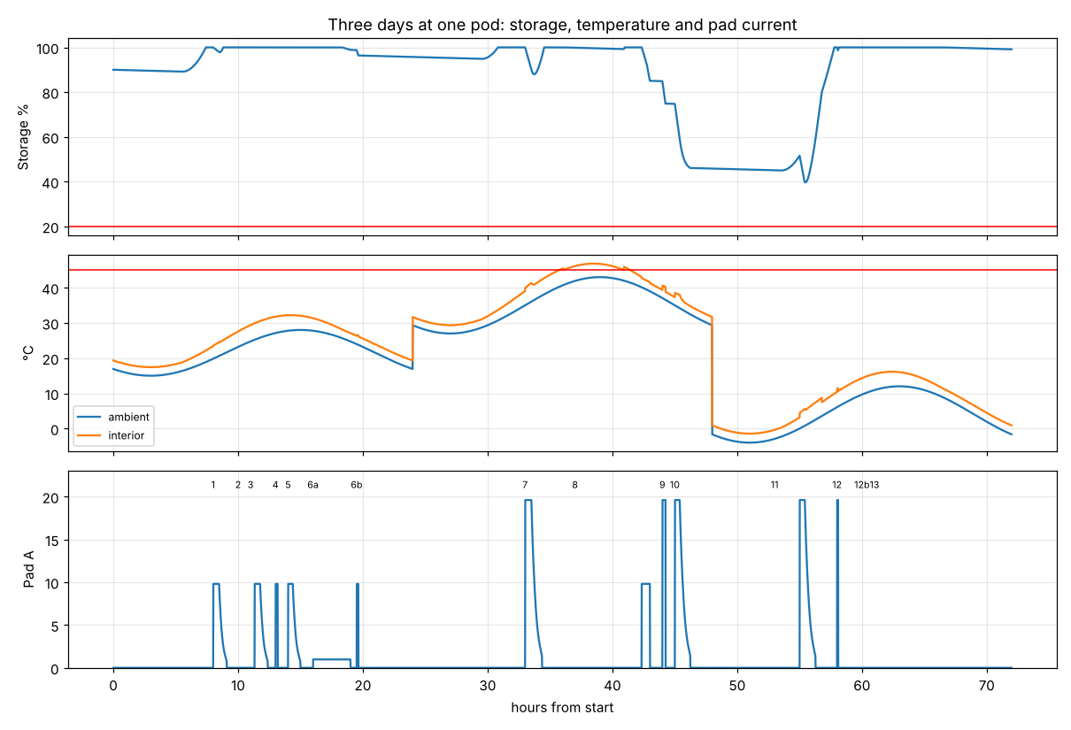
The last check runs every model together, in sequence, over three days at one pod with the large solar kit and grid kit, at 1 s steps (simulation package, section 11). In each step:
- sun and ambient set the solar controller (25 A cap) and the grid rules;
- storage is balanced;
- case temperature follows from the live internal losses;
- a drone lands on the finite pad with σ = 100 mm scatter and a random heading;
- the component-level sense circuit, from one randomly built pod, checks the pad;
- the same reference controller used in the fault simulations decides;
- the pack charges through the CC/CV physics with 0.25 A of avionics draw;
- the drone's BMS watches its cells.
The three days are mild (15–28 °C), hot (27–43 °C) and cold (−4 to 12 °C). The 10 µs electrical transients are covered by simulation 6; here the controller runs at 1 s.
| # | Event | Expected | Outcome |
|---|---|---|---|
| 1 | Quad at 25% | Charge to taper | Charged to 91%; peak cell 4.09 V |
| 2 | Quad at 95% | Refused, no fault | “Already full”; pad never powered |
| 3 | Quad on a wet pad (30 kΩ film) until it dries | No power while wet | Waited 20 min unpowered; then charged to 91% |
| 4 | 2 Ω metal bridge appears 10 min into a charge | Fault | Caught by the 1 s re-check; 255 J into the bridge |
| 5 | First landing off the field | Re-land, then charge | One re-land; charged to 91% |
| 6a | 5S pack at 40% on the quad route | Ends safely | Stayed in C/10 pre-charge; timer ended it at 3.85 V per cell |
| 6b | 5S pack at 80% on the quad route | Drone BMS stops it | BMS opened at 4.25 V per cell; pod ended without a fault |
| 7 | VTOL at 20%, hot morning | Charge to taper | Charged to 91%, briefly derated |
| 8 | VTOL at 41 °C ambient, full sun | No charge (interior above 45 °C) | Ended at once, “interior temperature” |
| 9 | Converter fails high during a charge | Hardware trip | Cut by the overvoltage comparator |
| 10 | VTOL after two faults | Charge (no lockout yet) | Charged to 91% |
| 11 | VTOL at −3 °C dawn | Wait for 0 °C, then charge | Waited 120 min unpowered; charged to 91% |
| 12, 12b | Bridges on two more charges | Faults; lockout on the third within 24 h | Fault, then lockout |
| 13 | VTOL at the locked-out pod | Not powered | Pad never powered |
All 15 events ended as expected. On every one of the 259,200 steps:
- the pad was never powered without a drone, nor without a passing sense check immediately before power;
- no charged 6S cell exceeded 4.09 V, and the misloaded 5S pack stopped at 4.25 V per cell by its own BMS;
- storage never fell below 49%;
- lockout came at exactly the third electrical fault in 24 hours.
The integrated run found two things the separate simulations had not, both now corrected in this document and the code:
- Drone BMS cutoffs counted as faults. A drone BMS opening its pack (or a drone lifting off) showed up on the re-check as an open pad and was counted as an electrical fault toward lockout. An open pad now ends the charge without a fault; a parallel path is still a fault.
- The heat envelope was overstated. On the 43 °C day the interior passed 45 °C from sun alone at about 40 °C ambient. No charge could start, and the storage BMS blocked solar charging for about 5 hours. The stated envelope is now full rate to 34 °C, reduced to about 40 °C, and no charging above about 40 °C in full sun. At the 45 °C stop point the interior overshot by up to 1.1 °C for one 1 s step before the rule acted.
A doc-to-code audit then checked the exported text of this document against the code. All 38 design values the code relies on (re-run for release 1.1.0) appear here with the same numbers, from the CV setpoint and trip thresholds to the sense resistors, strip dimensions, heat-sink rating and anchor rating. No superseded value appears outside a sentence that says it was superseded. The overvoltage band derived from part tolerances (24.91–25.19 V) lies inside the specified 24.89–25.21 V.
What this verification does and does not establish. It shows that the design is internally consistent: the document, the parameters, the controller logic and the physics models agree, and the combined system behaves as specified across the scripted events. It does not show that the models match the parts that will be built. That still takes a third independent review, ideally by a licensed electrical engineer, and the bench and field tests listed under Open questions.
Stress test: weather, power and failures
The stress test drives the full system through random and extreme conditions, plus failures of the protection hardware itself (simulation package, section 12).
Randomized campaign
400 independent campaigns of two days each (800 pod-days, 2,699 drone visits), at 1 s steps, each drawn at random:
- Weather: daily temperatures from −25 to 46.5 °C; cloud cover from overcast to clear; rain in 257 campaigns (wet-pad films 2 kΩ–2 MΩ); snow cover on the pad in 131.
- Power: storage starting anywhere from 12% to full; grid kit in 242 campaigns, with outages in 173; one solar panel failed in 86 and the solar controller failed in 77.
- Drones: random arrivals, route types and arrival charge; avionics draw 0–0.3 A; 155 misloaded 5S packs; 56 drones lifting off mid-charge.
- Failures: 202 injected electrical faults (metal bridges of 0.5 Ω–5 kΩ across the strips, converter runaways, pad shorts); an ambient sensor stuck at a wrong value in 25 campaigns.
- Build: a fresh random tolerance build of the sense circuit in every campaign.
Safety rules checked on every one of 69 million simulated seconds:
- no pad power without a drone and a passing sense check;
- no charged 6S cell above 4.20 V;
- no cell charged outside 0–45 °C;
- no film drawing more than 50 mW while powered;
- at most 600 J into any bridge or short;
- storage charge current at most 40 A;
- no charging with the interior above 46.5 °C.
Every visit that ended without a charge was also checked for a valid physical reason.
Result: zero safety violations and zero unexplained refusals. 1,646 of 2,699 visits were served. Every one of the other 1,053 had a valid cause:
- an injected fault (165);
- a drone lifting off (46);
- a misloaded 5S pack stopped by its BMS (98);
- the rest, cold below 0 °C, no stored energy, a wet or snow-covered pad, or a hot interior, alone or together.
Worst values seen:
- 6S cell 4.199 V;
- storage charge current 25.0 A;
- interior while charging 45.0 °C;
- 467 J into a bridge before the re-check cut it.
Storage drained to the 10% load disconnect in 5 campaigns that started low. It recovered in both campaigns where usable power returned. In the other 3 no usable power came back within the run: there was no sun and no grid, or it stayed below 0 °C, where the storage battery cannot be charged.
Named extremes
| Scenario | Result |
|---|---|
| 10 dark days with the grid down, then sun | Drone charging stopped at the 20% reserve (storage minimum 29%); VTOLs refused for lack of energy; service resumed when the sun returned. No violations |
| Heat wave, 30–48 °C, full sun, no grid | Charging only in cooler hours (interior start limit 43 °C); 7 of 11 visits served; peak interior while charging 43.3 °C. No violations |
| Deep freeze, −25 to −5 °C, with snow cover | No charging at all: drone cells and the LiFePO4 storage cannot charge below 0 °C, and snow covers the contacts. No violations |
| Monsoon: conductive rain films, a 1 Ω bridge, a pad short and a converter runaway | Pad stayed unpowered on low-resistance films; all three faults cut (at most 96 J into the bridge). No violations |
| Ambient sensor stuck at 20 °C on a −15 °C day | The pod tried, but every drone BMS blocked charging by its cell NTC. No cell charged below 0 °C |
Failures of the protection hardware itself
Each case below is run with the worst electrical fault, a converter running away to its input voltage, at 5%, 50% and 85% drone charge, for both drone types, at 10 µs resolution.
| Protection failure | Pad unpowered within | Peak current | Charge added after the fault |
|---|---|---|---|
| Hardware comparators dead (firmware alone) | 0.5 ms | 97 A | 0.013 mAh |
| MOSFET switch stuck closed (relay breaks it) | 15.3 ms | 150 A | 0.61 mAh |
| Switch stuck and comparators dead | 15.5 ms | 150 A | 0.63 mAh |
| Firmware hung (comparators alone) | 0.3 ms | 81 A | 0.002 mAh |
| Firmware hung and comparators dead (watchdog) | 98.5 ms | 150 A | 4.1 mAh |
| Hung, comparators dead and switch stuck | 113.5 ms | 150 A | 4.7 mAh |
| Current sensor reads zero | Charge ends early (taper) or hardware trips | — | — |
| Voltage sensor reads low or high | Undervoltage or overvoltage fault at once | — | — |
In every case the pad is unpowered and the added charge is at most 4.7 mAh on a 22 Ah pack, far too little to move a cell's voltage. These cases set four new specifications, now in the parts list and controller sections:
- an isolation relay rated to break at least 150 A DC at 32 V;
- a 30 A fast-acting fuse on the pad output;
- contacts rated 150 A for 20 ms;
- an independent 100 ms hardware watchdog.
Design changes from the stress test
- Interior start limit. No charge starts while the interior is above 43 °C; the pod waits for it to cool. Without this, a drone arriving into a hot case started and was stopped a second later.
- Backup hardware. The relay break rating, pad fuse, contact short-time rating and watchdog listed above.
- Wet films. With a pack present, films above about 47 kΩ are accepted, because they draw at most about 0.5 mA; lower ones are rejected.
What “works no matter what” can and cannot mean
The stress test supports a narrower and more useful claim: under every condition tried, alone or combined, the pod never did anything unsafe, and it never refused a drone without a physical reason. It does not, and cannot, charge in every condition:
- Below 0 °C neither the drone's cells nor the LiFePO4 storage can be charged safely. Cold sites need battery heaters, which this design does not yet include.
- Above about 40 °C in full sun the case is too hot. Hot sites need shade over the case, or a grid kit for evening charging.
- With no sun and no grid, charging stops at the 20% storage reserve until power returns.
- A snow-covered or heavily wetted pad cannot make or keep safe contact.
- A drone pack without a per-cell BMS is not protected against a wrong cell count; the BMS is mandatory.
- Three simultaneous independent failures (pad switch stuck closed, relay welded and both protection paths dead) leave only the pad fuse and the drone BMS. That is accepted as residual risk.
The models still use representative, not measured, part data, so the hardware tests and an independent professional review listed above remain the remaining steps.
Independent reviews and how each finding was resolved
First review: revision 1 → revision 2
An independent reviewer was given only the design reference and this package. It was asked to find errors, not to confirm the design. It ran the code on a separate copy. Each finding below was reproduced before it was fixed.
| # | Severity | Finding (revision 1) | Disposition (revision 2) | Verified by |
|---|---|---|---|---|
| 1 | Critical | Sense window accepts a 5S pack or a 6S pack with a shorted cell; charging to 24.6 V puts 4.92 V on each cell. The pod cannot read cell count. | A per-cell drone BMS is a binding requirement: OV 4.25 V, NTC charge window 0–45 °C, charge OCP ≥ 35 A, and a charge FET opened before arming. The limitation is stated plainly. | test_sense_cannot_identify_cell_count_so_drone_bms_is_required |
| 2 | Critical | OV comparator on a 1 % divider with a 0.5 % reference trips anywhere from 24.8 to 26.0 V. | Own 0.1 % divider and 0.2 % reference: 25.30–25.50 V. The 25.2 V full-charge mode is removed. | test_cv_with_tolerance_stays_below_comparator_band; fault cases at both band edges |
| 3 | Major | Converter runaway drives 52–125 A; the relay would have to break it. | Pad-side MOSFET switch with hardware OV/OC opens within 1 ms at every SOC, with a 150 A interrupt rating. The relay isolates only. | test_converter_runaway_cut_by_hardware_within_1ms (firmware disabled, 4 SOC × 2 band edges × 2 packs) |
| 4 | Major | A pad short is detected only if the current limit has failed. | Undervoltage trip (pad 2 V below the sense reading). | test_pad_short_with_working_current_limit_trips_on_undervoltage |
| 5 | Major | Pre-charge, START/WAIT, LOCKOUT, relative overcurrent and leakage claims are in the doc but not the code. | All implemented in controller.py and tested. The leakage claim is removed. | test_lockout_precharge_reserve_and_cold and fault tests |
| 6 | Major | Type-mismatch detection is claimed but has no mechanism. | Claim removed; the drone BMS covers it. | Doc text |
| 7 | Major | The LT4320 rectifier is probably active, not on body diodes; split chips may route return current through body diodes. | One ideal-diode pair per contact. The sense Monte Carlo draws both active and body-diode modes. | sense_hw.monte_carlo (1,200 builds) |
| 8 | Major | A flat storage battery can strand the pod. | Load disconnect at 10 %; BMS keeps its charge path open in undervoltage; latching grid relay forced on below 15 % by hardware; reserve abort. Bench start-up test listed as open. | test_lockout_precharge_reserve_and_cold (reserve abort); open question 7 |
| 9 | Major | Pad temperature used as cell temperature. | Drone BMS NTC plus a shaded ambient sensor. Analysis shows the pad reaches 42–61 °C in sun. | test_pad_runs_hotter_than_45c_in_sun |
| 10 | Major | Case thermal design asserted, not analysed. | Lumped model shows a sealed case reaches 53 °C at 25 °C ambient. Heat-sink plate, white case and side shading are required; derate above 35 °C (superseded in release 1.0.1: derate above 34 °C). | test_thermal_needs_heatsink_and_shading |
| 11 | Minor | Energy simulation never reaches the current cap; lockout latency not modelled. | Bounded analytically: solar ≤ 25 A (MPPT setting); a 1–2 s lockout latency gives ≤ 37 A transient, within the 50 A BMS and fuse ratings. | test_worst_case_peak_current_with_lockout |
| 12 | Minor | Open pad can read 27.48 V, inside the window. | 29.5 V boost and a 0.1 % divider: the open pad reads ≥ 28.5 V. | test_sense_hw_monte_carlo_tolerances_and_temperature |
| 13 | Minor | Five contacts not redundant (one lost: about 21 % failures); finite pad not modelled. | Nine contacts, 3 × 3 at 150 mm; 110 mm strips. Tolerates any two failed contacts and ±10 mm build error; finite pad ≥ 99.997 % at σ = 100 mm. | test_nine_contact_grid_never_fails_even_with_two_contacts_lost, test_finite_pad_with_landing_scatter |
| 14 | Minor | Per-cell figures misstated; sense.py values differ from the parts list; diode temperature sign; storage voltage at 20 %; tuned grid credit. | Corrected to 4.12 V per cell; params aligned; −2 mV/K diode model; 26 V at rest; 80 % credit stated as a design choice with its basis. | Code and doc |
| 15 | Minor | Q1 gate drive, ADC buffer, boost pass-through, avionics draw at termination, relay coil power, live grid port, lift-off arcing, two drones. | Zener gate clamp; buffered ADC with external reference; boost with true disconnect; C/20 + 0.3 A termination plus a 3 h timer; latching and switched relays; ideal diode on grid input; BMS charge FET opens before arming; one-drone-per-pod operating rule. | Doc text |
Areas analysed for the first time in revision 2 (analysis.py, notebook sections 8–10):
- thermal;
- wind uplift and anchoring;
- snow load;
- enclosure pressure;
- contact resistance and heating;
- magnetic field during charging;
- tag visibility and camera specification;
- drone mass and range;
- wiring voltage drop;
- surge protection;
- RF emissions;
- storage cycle life;
- flat-battery recovery.
What remains unverifiable without hardware is listed under "Open questions" in the design reference.
Second review: revision 2 → revision 3
A second reviewer, again given only the design reference and this package, found 2 critical, 8 major and 9 minor problems. It also found that four of the revision 2 fixes above (#5, #9, #10, #11) were wrong or incomplete in code. Each finding was reproduced before it was fixed.
| # | Severity | Finding (revision 2) | Disposition (revision 3) | Verified by |
|---|---|---|---|---|
| C1 | Critical | WAIT never checked for an empty pad: after the drone left, recovering storage powered an empty pad. | WAIT and START drop to IDLE on an empty pad. A fresh two-level sense check is required immediately before power. | test_wait_then_drone_leaves_never_powers_pad |
| C2 | Critical | A resistive bridge across the strips while a drone charges was never detected: the pack holds the voltage and CC holds the current. | Two-level sense re-check every 1 s in a 20 ms pause (2 % duty). Any parallel path below about 100 kΩ fails it; ≤ 0.2 kJ reaches a bridge. | test_bridge_across_strips_with_drone_present_is_caught_within_1s (5 resistances × 2 packs); test_sense_rejects_pack_with_parallel_film_below_100k |
| M1 | Major | Pad temperature still gated charging in code; the 80 °C alarm and 42 °C derate were missing. | Pad temperature removed from gating; 80 °C pad alarm (fault) and 42 °C interior derate (halves current) implemented. | test_hot_pad_does_not_block_or_fault_but_80c_does, test_interior_derate_halves_current |
| M2 | Major | The 0.85 heat-sink fraction was a chosen input; with real mounting the interior failed. | Fraction derived from mounted parts. The MPPT moves onto the plate (87 %); plate 0.25 K/W. A test shows the MPPT-inside case fails. | test_thermal_needs_heatsink_and_shading |
| M3 | Major | Switch turn-on was never simulated, and either ordering would trip. | Converter pre-biased below the pack, 100 ms current ramp, UV blanked during ramps. Simulated from START through pre-charge. | test_turn_on_from_start_ramps_without_trips_and_leaves_precharge |
| M4 | Major | OV band 25.30–25.50 V is 4.22–4.25 V per cell, above the cell limit. | Nominal 25.05 V; band 24.89–25.21 V (≤ 4.20 V per cell), 0.17 V above CV max. | test_ov_band_derivation_and_why_one_percent_fails |
| M5 | Major | Comparator band hard-coded, not derived; drift and offset ignored; no latch. | ov_band() derives the band from tolerances, drift and offset. Comparators latched; latch handling around the sense check specified. Runaway tests run at both band edges. | same, plus runaway tests at 24.89 and 25.21 V |
| M6 | Major | Pre-charge threshold ambiguous by the rectifier offset (0.04–1.25 V); stale UV reference. | 10 s C/10 probe; pre-charge exit judged on pad voltage under current; UV uses the running maximum during the charge. | test_deeply_discharged_pack_stays_in_precharge |
| M7 | Major | Environment and timer ends counted toward lockout; avionics draw unbounded and unmodelled. | Only electrical faults count. Avionics ≤ 0.3 A is a drone requirement; the plant models avionics draw. | test_hot_ambient_ends_without_fault_and_never_locks_out |
| M8 | Major | Reserve abort skipped whenever a grid kit was present, even during an outage. | Conditioned on grid current actually flowing (> 1 A). | test_lockout_and_reserve_abort_conditions |
| new | Major | Found while fixing M3: a full pack landing held the pad inside the OV band and faulted on every visit. | A sense reading ≥ 24.4 V ends the session as "already full", with no power and no fault. | test_full_pack_is_not_powered_and_not_faulted |
| m1 | Minor | No clamp on the pad switch opening 30–80 A. | Bidirectional TVS and RC snubber specified. | Doc |
| m2 | Minor | The 37 A transient exceeds a 25 A storage charge rating; energy cap test circular. | Storage charge rating ≥ 40 A; circular test removed. | Doc; test removed |
| m3 | Minor | Camera numbers assumed a square image. | Worst-heading model with aspect ratio: 4:3 gives 0.42 m, 16:9 gives 0.56 m; 4:3 specified. | test_tag_and_camera_spec |
| m4 | Minor | Pad modelled as a black body; drone pack heating not modelled. | Pad ε 0.05: 50–65 °C. Drone pack heating is an open question (its NTC governs). | test_pad_runs_hotter_than_45c_in_sun |
| m5 | Minor | Anchors sized for uniform uplift; test checked 30 m/s. | All uplift on the windward pair; ≥ 1.5 kN anchors; test at 35 m/s. | test_wind_uplift_exceeds_weight_above_about_18_ms |
| m6 | Minor | Storage life overstated for grid sites. | Computed from energy-balance logs: about 4 y (3,000 cycles) / 8 y (6,000) at a grid VTOL site. | Notebook section 10 |
| m7 | Minor | Subtotal did not match the rows; 21 A vs 27 A wording; force-on vs lockout precedence. | Row prices updated, subtotal ~$1,800–2,600; precedence stated (hardware force-on wins). | Doc |
| m8 | Minor | Stale docstrings, unused duplicate thresholds, plant pad voltage omitting contact resistance. | Fixed; thresholds live only in controller.Limits. | Code |
| m9 | Minor | Some "verified by" tests did not test the fix. | Replaced: derived thermal fraction, exhaustive two-contact-loss grid, comparator derivation, bridge, WAIT, turn-on. | 86 tests |
Final integrated verification (revision 3)
mission.py runs every model together. Fifteen scripted events over three days all end as expected, and the invariants hold on all 259,200 steps. Two further corrections came out of this run:
| Finding | Correction | Verified by |
|---|---|---|
| A drone BMS opening its pack, or a drone lifting off, appeared on the 1 s re-check as an open pad and counted as an electrical fault toward lockout. | An open pad on the re-check ends the charge without a fault ("pack disconnected"); a parallel path remains a fault. | test_bms_opening_or_liftoff_ends_without_fault; mission event 6b |
| The thermal envelope was overstated. In full sun the interior passes 45 °C at about 40 °C ambient with no drone charging, and the storage BMS blocks solar charging. | Interior above 45 °C ends a charge (no fault). Stated envelope then: full rate to 35 °C, reduced to about 40 °C, none above about 40 °C in full sun (superseded in release 1.0.1: full rate to 34 °C, half rate to about 40 °C). | Mission event 8; test_mission_invariants |
audit.py: all 36 design values used by the code appear in the design reference with the same numbers, and no superseded value appears outside a historical sentence.
Stress test (revision 3)
The full system was run through 400 random two-day campaigns (800 pod-days, 2,699 drone visits), 5 named extremes and 6 protection-hardware failure combinations. The random campaigns covered weather from −25 to 46.5 °C with rain and snow, storage starting from 12 %, grid outages, failed panels and solar controllers, misloaded packs, lift-offs, 202 injected electrical faults and stuck sensors.
Result: zero safety violations and zero unexplained refusals.
Corrections the stress test produced:
| Finding | Correction | Verified by |
|---|---|---|
| A drone arriving into a hot case started charging and was stopped one second later; the interior read 47–48 °C while charging. | No charge starts above 43 °C interior; the pod waits for it to cool. | test_stress_random_scenarios; mission event 8 |
| Protection-hardware failures need backup ratings: with the switch stuck closed, the relay must break up to 150 A; with firmware hung and comparators dead, only a watchdog acts. | Relay rated to break ≥ 150 A DC at 32 V; 30 A fast pad fuse; contacts rated 150 A for 20 ms; independent 100 ms watchdog. | test_protection_component_failures_still_unpower_pad |
| Test-criterion correction: films above about 47 kΩ are accepted with a pack present. They draw at most 0.5 mA, so the safety criterion is film power, not the presence of water. | Documented; the invariant is film power ≤ 50 mW while powered. | Stress invariants |
On-board solar charging (both airframes): independent review of the first model
An independent reviewer read drone_solar.py and drone_verify.py against the pod design and controller. All ten findings were corrected before the published results.
| # | Finding | Correction | Verified by |
|---|---|---|---|
| 1 | In-flight solar had no defined path: the charge FET is open in flight, so the charge-port charger cannot reach the bus. | Separate ideal-diode output onto the discharge bus, enabled only when armed, inside the temperature window, not locked out, limited to the measured load; a load-follow failure is a stress fault. | Mission event 1; net charge in flight invariant; stress fault load_follow_fail |
| 2 | Shade counted twice (irradiance cut and bypass loss); MPPT input floor ignored. | Electrical model uses unshaded irradiance with bypass loss only; output is zero when the remaining substrings fall below 6 V. | test_shade_counted_once_and_mppt_floor; mission event 11 |
| 3 | Panel electrical draw and charger loss taken at full MPP power even when the charger drew less (energy not conserved). | Panel draw = charger output + loss; whatever is not drawn stays in the panel as heat. | test_energy_balance_of_charger_closes |
| 4 | One lumped pack node hid the face cells under the panel. | Two-node pack (face, core); charger NTC on the face, BMS NTC in the core; charging needs both. | Direct-mount sensor-fault extremes; test_direct_mount_is_defeated_by_one_low_reading_face_sensor |
| 5 | Heater ignored the interlock and lockout; heater power path and awake draw unaccounted. | Heater gated on the solar enable; fed from the charger output with the charge switch open; awake draw recorded against the 0.3 A budget (drone sleeps on the pod). | Named extremes; pod consistency checks |
| 6 | "Unexplained refusal" counter copied the controller's own flags, so it could not catch a fault. | Judged from true temperatures, voltage, pod current and BMS state; refusals with an injected fault are counted separately. | Stress campaign: 0 unexplained |
| 7 | The pod could charge a pack at 1 C below 10 °C (lithium plating). | Drone presents the pack to the pod only at 10–35 °C and opens its FET if either sensor falls below 10 °C during the charge; plating invariant added. | Stress campaign (3 plating violations found and removed by this rule) |
| 8 | Pod sub-model had no fault path; interlock read internal pod state the drone cannot observe; sense used rest voltage. | Pod OV fault at the bottom of the hardware band with lockout at 3; sense decisions use the measured terminal voltage; the same-step interlock is justified by the 1 ms hand-off transient (≤ 100 ms overlap). | test_handoff_transient; double-fault extreme |
| 9 | CV tolerance applied twice in the invariant. | Limit = nominal CV × (1 + tolerance). | test_cv_tolerance_worst_case_stays_at_or_below_4_12V |
| 10 | Four solver passes did not converge with both chargers on. | Iterated to convergence (1e-10 A). | Interlock-failure extremes |
Further findings from the drone simulations themselves:
- Mounting. A pack directly under the panel stops solar charging above about 27 °C and reaches 68–70 °C on a 45 °C day; a single low-reading face sensor then lets face cells charge above 45 °C. Direct mounting is rejected; a vented gap with reflective faces is required.
- Solar must be gated by the BMS charge-allow signal. Otherwise the solar charger holds the shared rail at 24.6 V while the BMS FET is open, the pod reads a full pack and never charges.
- BMS overvoltage must release only after discharge. Otherwise a misfitted 5S pack is pushed to 4.25 V on every pod sense cycle.
- Quad flight heating. An 18-minute hover raises the quad pack about 30 K; this, not solar, sets its temperature, and delays pod charging by up to about 2 h at 30 °C ambient. High-power cells are specified.
Release 1.0.1 corrections (site-build review, 2 November 2026)
| Finding | Correction | Verified by |
|---|---|---|
Parts list gave the OV comparator a 0.2% reference; the design section and controller.ov_band() use 0.1%. A builder following the binding parts list would get a wider trip band. | Parts list now reads 0.1% / 10 ppm/K divider and 0.1% / 20 ppm/K reference. | Audit check "OV reference tolerance"; stale-value scan for "0.2% reference" |
| "Full rate to 35 °C ambient" contradicted the model: the interior is 42.2 °C at 35 °C ambient, above the 42 °C derate point. | Interior reaches 42 °C at 34.8 °C ambient; envelope restated as full rate to 34 °C, half rate to about 40 °C. | test_full_rate_envelope_is_34C_not_35C; audit check "Full-rate thermal envelope" |
| The pod's 20 A VTOL setting is 0.9C on the modelled 22 Ah pack but about 2.2C on a ~194 Wh pack such as the L1-W's; the on-board solar results use representative airframes, not the L1. | Design reference now states the two settings are valid only for the reference packs, requires current ≤ the lower of 1C and the cell maker's limit for any other pack, and labels the on-board solar results as not L1 figures. | Design reference, Drone charger and On-board solar sections |
| Release notes used site wording for the small kit that the rest of the design does not use. | Reworded to "temporary or small sites". | — |
Release 1.1.0: the L1 aircraft and site-build corrections (2 November 2026)
The L1-Q and L1-W (L1 design reference v2.2.1, 6S2P Molicel P45B) were run through the pod and on-board solar models (podsim/l1.py, tests/test_l1.py, notebook section 14).
| Finding | Correction or result | Verified by |
|---|---|---|
| The pod's 10 A and 20 A settings are 1.1C and 2.2C on the 9.0 Ah L1 pack; 20 A also exceeds the cell maker's 2C maximum. | New "L1: 9 A" setting (lower of 1C and the maker's 18 A). 30 % to taper in 0.86 h; cells at most 4.095 V. | test_pack_and_pod_current |
| Protection had not been run on the L1 pack. | All cases pass: runaway cut by hardware within 0.33 ms; six protection-hardware failures within 113.5 ms and 125 A; short, lift-off and sensor failures. | test_protection_holds_for_the_l1_pack |
| Pod-kit mass missing from the L1 weights. | With 0.35 kg added (kit and BMS): legs 7.2 km (L1-Q) and 29.5 km (L1-W) in still air; design spacing in a 5 m/s headwind 3.8 km and 19.2 km. | test_kit_mass_cuts_range_and_spacing |
| Listed landing camera (IMX296, 6 mm lens) fails the 120° and 1,920 px requirement. | 45° and 1,456 px; tags leave view below 1.75 m. A wide lens on the same sensor decodes only below 3.8 m. Camera must change. | test_listed_camera_fails_the_landing_requirement |
| L1 has no per-cell BMS, no charge FET and no balancer. | Requirement stated; fit before pod use. | Design reference, L1 gaps |
| Contact-plate fit unconfirmed for L1 airframes. | A 200 mm grid works on strips scaled to 73 mm / 10 mm, but the universal 300 mm grid fails 7 % of landings on them: a separate L1 pad if the 300 mm plate does not fit. | test_smaller_contact_grid_works_only_on_its_own_strips |
| Mounting rule for the L1 panels. | Vented gap holds the pack at 52–54 °C on a 45 °C day; directly under the panel it reaches 69 °C. | test_mounting_rule_holds_for_l1 |
| Genasun GVB-8-Li lacks enable, temperature input and latched OVP; 6 mA night drain. | External output switch, interlock, NTC gating and OVP required. | Design reference, L1 gaps |
| Solar charger kept "done" one step after the pack fell below the 4.00 V/cell restart level (a 10 s lag found by the availability check). | Restart evaluated before the current is computed. Drone stress campaign rerun: 0 violations, 0 unexplained refusals. | drone_stress_results.json |
| SHA256SUMS.txt listed itself. | Excluded from its own list. | Release check |
sense_hw.py comment still gave the OV comparator a 0.2 % reference, and the stale-value scan missed the spaced form. | Comment corrected; scan now catches both forms and runs over the code and README. | test_stale_values_absent_from_code_and_release_text |
| Duplicate controller-table sentence; old package name in the design reference. | Removed; package name updated. | Audit 38/38 |
Release 1.1.1 corrections (site-build review of 1.1.0, 2 November 2026)
| Finding | Correction | Verified by |
|---|---|---|
| Main design sections still described a two-position drone-type switch; only the L1 section had the 9 A position. | Design principle, Drone charger, configuration settings, controller states, parts list and Setup step 2 now give three positions: quad 10 A, VTOL 20 A, L1 9 A. | Design reference |
| L1 pack-heat figures (4.4, 5.4, 21.6 W) did not match the stated 42 mΩ. | The model uses 42 mΩ ohmic plus 12 mΩ polarization; the figures are steady-state I² × 54 mΩ. The text now states both; thermal results already used the same model, so no result changes. | l1.pod_charge_table |
| In-flight solar: the summary gave the L1-W 63–73 %, the paper only +73 %. | Paper now gives noon, 09–15 h average and December values for both aircraft, as gains in leg distance on the kit-fitted leg: L1-W +77 %, +66 %, +16 %; L1-Q +7 %, +7 %, +2 %. | l1.solar_endurance_table |
| Leg times on different bases (L1-Q excluded its hover, L1-W included 90 s of vertical flight). | Both reported as transit (sets the distance) and time in the air: L1-Q 10.0 / 10.8 min, L1-W 27.3 / 29.3 min. Distances unchanged. | l1.leg, notebook section 14 |
| ADC path reference listed as 0.2 %. | Deliberate: it is the ADC reference, separate from the OV comparator's 0.1 % reference; the parts table now says so. The sense Monte Carlo allows ±0.5 % ADC gain error. | Design reference |
Charging Pod · Pod design · L1 aircraft results · On-board solar · Sanctir L1