Sanctir L1 Charging Pod
A ground charging pod for the L1 program. A drone lands on the pad, charges in about an hour instead of most of a day on its own panels, and flies on. Pods along a route work like a charging network.
Simulated and reviewed, not built
Design Reference revision 3, 2 November 2026. Every design claim is backed by the simulation package: 165 pass/fail checks, a three-day integrated run, and stress campaigns covering weather, power and failures. CC BY 4.0 for documents, MIT for simulation code.
One pod, plug-in kits
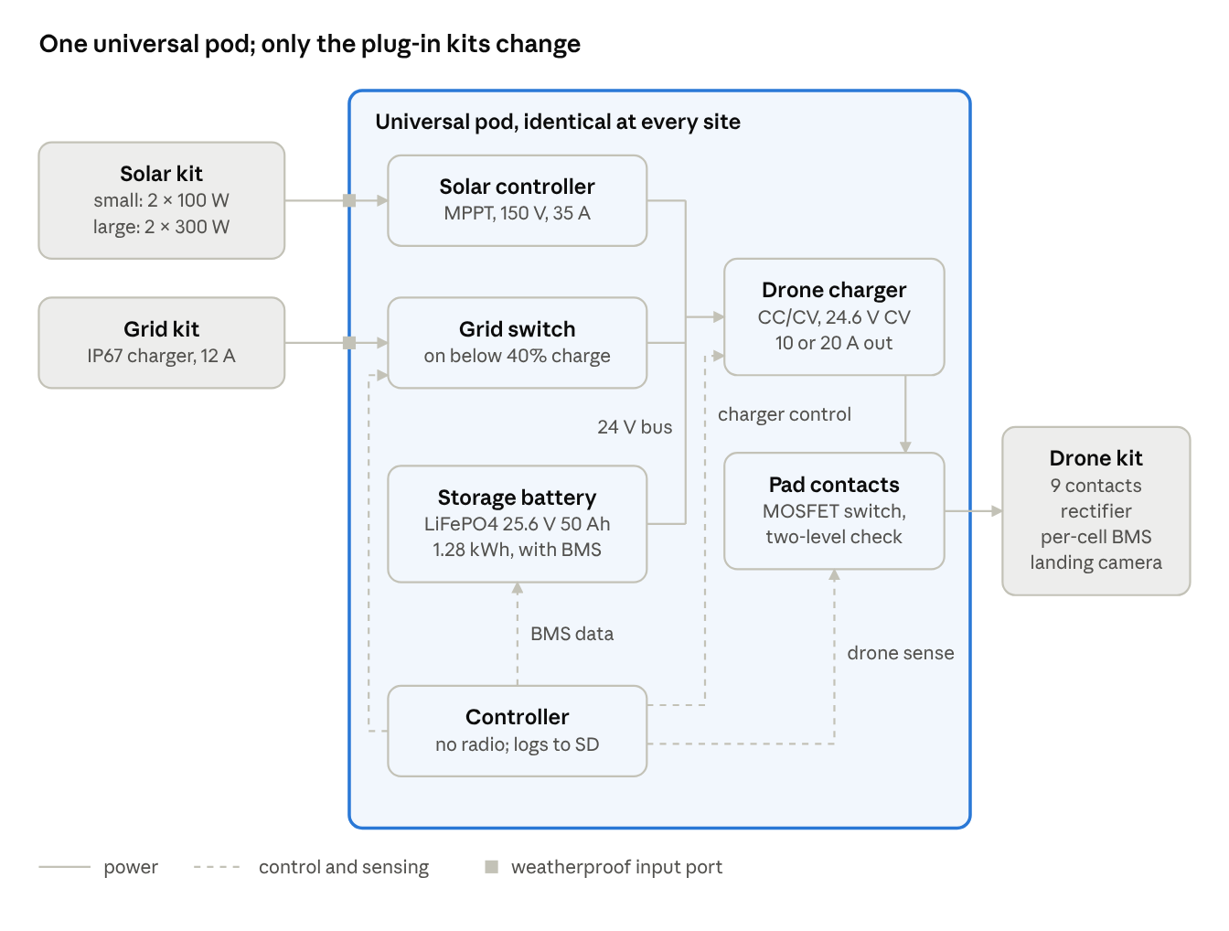
Every pod is identical: landing pad, charger, storage battery and controller in one weatherproof case. A kit plugged into its side ports adapts it to the site, so a pod can be built, tested and stocked as one part and assigned anywhere. The pod has no radio hardware and stores no mission data. Its pad carries no voltage until a drone’s battery is detected, and it rechecks every second while charging.
| Site | Plugged in | Behaviour |
|---|---|---|
| Fixed site with grid | Large solar kit and grid kit | Solar first; grid tops up below 40% |
| Remote, off-grid | Small folding solar kit | Solar only; the pod declines a charge it cannot finish |
| Grid only | Grid kit | Always ready; no solar |
Key results
All results are from simulation. Rows that do not name the L1 use the representative quad and VTOL airframes in the design.
| Area | Result |
|---|---|
| Charge time, from 25% | Quad (6S 10 Ah) about 1.1 h; VTOL (6S 22 Ah) about 1.3 h |
| Solar throughput | Large kit: about 7 quad or 3 VTOL charges per clear 4-peak-sun-hour day |
| Pod safety | 800 simulated pod-days: zero safety violations, zero unexplained refusals |
| On-board solar safety | 400 random scenarios with single, double and triple faults: zero safety violations |
| Temperature envelope | No charging below 0 °C; pod full rate to 34 °C ambient, half rate to about 40 °C, none above that in full sun |
| On-board solar, VTOL | About 75% of the pack refilled per clear summer day; +30–36% endurance in daylight flight |
| On-board solar, quad | 38% of the pack per clear summer day; costs 4–6% endurance in every flight |
| L1 pod charge | 9 A (1C): 30% to 85% in 0.57 h; all protection cases pass |
| L1 legs with pod kit | L1-Q 7.2 km (10.8 min in the air), L1-W 29.5 km (29.3 min) in still air |
Where there is no pod, or a pod is occupied or faulted, the drone charges from its own panels. The network speeds a mission up, and the mission never depends on it. Pods sit no farther apart than about 70% of the drone’s rated range, and route plans must never schedule two drones to one pod at the same time.
How a charge works
- Land. GPS brings the drone within view of the pad, and four AprilTags on its border guide the final landing. Heading does not matter: nine contacts under the drone reach both polarities at any angle.
- Check. The pad stays unpowered until a two-level, low-current sense check confirms a battery and not a film of water or debris.
- Charge. Current ramps up, runs at a fixed rate, then tapers at 24.6 V. Every second the charger pauses for 20 ms and repeats the sense check.
- Leave. The session is logged to an SD card for collection on site, and the drone flies on. Three electrical faults in 24 hours take the pod out of service until it is reset on site.
The drone’s own per-cell battery management system is mandatory. The pod cannot read cell count from voltage, so that system is the only protection against a wrong pack.
How this fits the L1
The pod can charge both L1 aircraft safely at 9 A in simulation, but neither aircraft can use a pod as listed today. This release runs the L1-Q and L1-W through the pod and on-board solar models with their own values. No L1 aircraft or pod has been built. See the full L1 results.
Charge setting. Use the new 9 A position on the drone-type switch, which is 1C on the L1’s 9.0 Ah pack. Do not use the 10 A position (1.1C) or the 20 A position (2.2C, above the cell maker’s 18 A maximum) on an L1 pack.
Range and pod spacing, with the 0.30 kg pod kit and about 0.05 kg for the battery management board the L1 lacks:
| Aircraft | Published leg | Leg with kit | Design spacing, still air | Design spacing, 5 m/s headwind |
|---|---|---|---|---|
| L1-Q | 8.9 km | 7.2 km | 6.5 km | 3.8 km |
| L1-W | 36.3 km | 29.5 km | 26.5 km | 19.2 km |
What must change before an L1 uses a pod:
- Battery. Fit a per-cell battery management board with a charge switch the flight controller can open before arming, and an active balancer. The L1 parts lists have neither.
- Landing camera. Fit a camera that meets the specification. The listed camera fails on field of view and pixel count.
- Solar charger. Add an output switch and pod interlock. The listed charger has no enable or battery temperature input and no published latched overvoltage protection.
- Flight software. Write and flight-test seven pieces of pod software. None exists in L1 version 2.2.1, and this release contains no firmware or flight software. Its controller model only checks the design’s logic and cannot run on a pod.
- Still to confirm. The panel gap over the battery, the contact plate fit on each airframe, and the panel string voltages. These need L1 data that has not been set yet.
Read the design
- Pod design: schematic, subsystems, parts list and costs, sizing, siting and operations, safety, regulatory notes and open questions.
- L1 aircraft results: the 9 A setting, range and pod spacing, on-board solar, and each gap against the pod’s requirements.
- On-board solar charging: the drones’ own panels, mounting, daily yield, and the rules that keep them from conflicting with the pod.
- Verification: the simulations, the integrated three-day run, the stress tests and every finding from the independent reviews.
Downloads
- Design Reference, revision 3 (PDF, 52 pages)
- Complete release 1.1.1 (zip): the design reference, simulation notebook, review record, simulation code, tests, saved results and checksums.
The released files use the design’s earlier name, Solar Hop. To reproduce the results, install the requirements in simulations/ and run python -m pytest -q.
It is not a built or tested product. The simulations show the design is internally consistent; they do not show that the models match the parts that will be built. It comes with no warranty. Lithium batteries, high-current DC circuits and autonomous aircraft can cause fire, injury and property damage. Anyone who builds or operates it is responsible for an electrical engineer’s review, for the bench and field tests, and for the rules that apply where they build and fly it. The licences grant copyright permissions only. The prior-art search is not complete and no freedom-to-operate review has been done: see the open questions.
Licence and citation
Documents and figures: CC BY 4.0. Simulation code: MIT. Anyone may use, modify, build and sell from the design, with credit.
George, C. B. (2026). Solar Hop Universal Charging Pod: Design Reference, revision 3, release 1.1.1. Sanctir. https://sanctir.com/l1/pod/
AI disclosure. AI assistance was used for source retrieval, verification against primary sources, and editing for tone and clarity. The analysis, judgments and text are the author’s, and the author is responsible for the content and any errors.
Discuss the design
Corrections, test results and questions about the design are welcome.
Pod design · L1 aircraft results · On-board solar · Verification · Sanctir L1