L1 Charging Pod: Design
The schematic, subsystems, parts list, sizing, operations, safety and regulatory notes from Design Reference revision 3.
Simulated and reviewed, not built. No pod has been built or tested. The models use representative part data. Results for the L1-Q and L1-W are on the L1 aircraft page; neither can use a pod as listed today. A licensed electrical engineer’s review and the bench and field tests listed in the design are required before anyone builds and flies it.
Bottom line
One charging pod serves every site. The pod itself — landing pad, charger, storage battery and controller in one weatherproof case — never changes. What changes is the power kit plugged into its two side ports: a large solar kit, a small folding solar kit, a grid kit, or a solar kit and a grid kit together.
A drone lands on the pad, charges in about an hour instead of most of a day, and flies on to the next pad or its recovery point. The pod needs no radio link, stores no mission data, and is safe to touch when no drone is on it. If a pod is dead or occupied, the drone falls back to charging from its own panels, so the network speeds the mission up but the mission never depends on it.
Design principle
Every pod is built the same way. Site differences are handled outside the case by plug-in kits, so a pod can be built, tested and stocked as one part number and assigned to any site. This works because the pod's inputs are sized beyond the largest kit: the solar controller accepts up to 150 V and 1,000 W of panels at 24 V, and the grid input is a separate weatherproof port that stays capped where there is no grid. The only per-route setting is a switch inside the case that selects the drone type (quad 10 A, VTOL 20 A, or L1 9 A for both L1 aircraft); the hardware is identical.
The operating rule is the same in every configuration. Solar charges the storage battery first. If a grid kit is attached, the controller switches it on only when the storage battery falls below about 40% charge and off again at about 80%. The drone charger draws only from the storage battery, never directly from a kit, so drone charging behaves the same whatever is plugged in.
| Configuration | Plugged in | Behavior | Typical site |
|---|---|---|---|
| Fixed site, grid available | Large solar kit + grid kit | Solar first; grid tops up below 40% | Rooftop, farm building, depot |
| Remote, off-grid | Small folding solar kit | Solar only; pod declines a charge it cannot finish | Field route, ridge line, temporary survey |
| Grid only | Grid kit | Always ready; no solar | Shaded or indoor site, test bench |
A remote site with room can take the large kit instead when it needs more daily charges. The pod does not need to know which kit is attached.
Engineering schematic
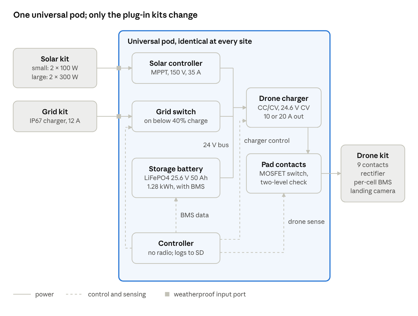
Either kit feeds the 24 V bus through its own weatherproof port; the drone charger draws only from that bus. The controller powers the pad contacts only after a low-current sense check confirms a drone battery is connected. The controller has no radio hardware: it reads the battery and solar controller over wires and switches the grid input and the charger.
Subsystem engineering
Storage battery
A 25.6 V, 50 Ah lithium iron phosphate (LiFePO4, 8 cells in series) pack, 1.28 kWh, with a built-in battery management system (BMS). At rest its voltage is about 26 V at 20% charge (lower under load) and reaches 28.4–28.8 V at the end of charging; the BMS disconnects near 20 V. LiFePO4 is chosen over the drone's lithium-ion chemistry because it tolerates thousands of full cycles and is much less prone to thermal runaway in a sealed case left in the sun.
The pack must meet four requirements: a BMS rated for at least 50 A continuous; a charge rating of at least 25 A (0.5C); a low-temperature charge cutoff (typically no charging below 0 °C); and a wired data port (RS-485, CAN or UART). Many packs ship with Bluetooth; choose one without it, or one where it can be removed.
Currents are moderate at 24 V. The largest load, a VTOL charge, draws about 23 A from the pack (about 540 W). The largest charge input, the large solar kit plus the grid kit, could reach about 33 A (about 21 A of solar plus 12 A of grid). The controller therefore turns the grid input off whenever solar current exceeds 13 A, which holds total charge current at or below 25 A. The solar controller's own maximum charge current is also set to 25 A, because the large kit alone can reach about 27 A in cold, bright sun. The main battery fuse is 50 A, on 6 AWG cable rated above that. It must be a Class T or MRBF-type fuse with an interrupt rating above the pack's short-circuit current.
Recovery from a flat battery. Several measures keep a pod from stranding itself after a long cloudy spell:
- Drone charging stops at the 20% reserve.
- A low-voltage disconnect drops every load except the controller's sleep supply at 10%.
- The BMS must keep its charge path open while it is in undervoltage cutoff, so the solar controller and grid charger can still reach the cells.
- The latching grid relay is forced on by a hardware comparator below 15%, independent of firmware. This takes precedence over the firmware's solar lockout, which is why the pack's charge rating must cover 37 A (40 A specified).
Whether the specific solar controller and grid charger start into a deeply discharged pack must be confirmed on the bench.
Solar input
A Victron BlueSolar MPPT 150/35 charge controller, rated 35 A and 1,000 W at 24 V. It is the model without Bluetooth and reports over a wired VE.Direct serial port. Two datasheet rules govern the panel strings:
- Panel voltage must exceed battery voltage by 5 V before the controller starts, and by 1 V while it runs.
- Open-circuit voltage must stay under 150 V in the coldest conditions (145 V to start).
Both kits are therefore two panels in series:
- Large kit: 2 × 300 W rigid panels. Each must have an open-circuit voltage of 40 V or less at standard test conditions (STC). The pair is then about 80 V at STC. Panel voltage rises in cold weather; at −40 °C, the NEC 690.7 correction puts the pair at about 100 V, still well under the 145 V limit. The 150 V controller is specified instead of a 100 V model because a 100 V model would be exceeded by common 72-cell 300 W panels (about 45 V each) on a cold morning.
- Small kit: 2 × 100 W folding panels. Each must have a maximum-power voltage of 20 V or more at STC. The pair runs at about 40 V. Panel voltage falls about 0.42% per °C as cells heat; at a 45 °C ambient (about 80 °C cell temperature) the pair drops to about 30.8 V, which still clears the 29.8 V the controller needs while finishing a charge (28.8 V plus 1 V). Simulation 1 showed 19 V panels fall to 29.2 V at that temperature and stop charging near full; the failure is lost output in extreme heat, not damage.
The large kit uses about 60% of the controller's rating. The controller's full output is rated up to 40 °C ambient (see Thermal design below).
Grid input
An external Victron Blue Smart IP67 24/12 charger (120 VAC version, 100–135 VAC input, 12 A output, about 300 W at bulk-charge voltage and about 340 W at absorption voltage). It lives outside the case and plugs into the grid port, so the pod never carries mains voltage. Its Bluetooth is turned off permanently in VictronConnect before deployment; that setting cannot be reversed. Inside the case, the grid input passes through an ideal diode and then a latching DC relay. The diode blocks reverse polarity and keeps the port pins dead when the lead is unplugged; the latching relay draws no coil power. A hardware comparator forces the relay on below 15% storage charge. The controller sets the relay:
- On below 40% charge, off at 80%. Both thresholds can be set; a grid-only site may hold a higher range.
- Off whenever solar current exceeds 13 A. The controller reads solar current about once a second over VE.Direct, so at a cloud edge total charge current can briefly reach 37 A (25 A solar plus 12 A grid) for up to about 2 seconds. That is within the 50 A BMS and fuse ratings.
Refilling from 40% to 80% (about 510 Wh) takes about 1.7 hours on grid alone. The grid also switches on whenever a drone is waiting that storage alone cannot finish, and the start decision credits 80% of the grid output over the charge. Without that rule, simulation 3 showed grid pods sitting idle with a drone waiting.
Drone charger
A buck-boost constant-current/constant-voltage (CC/CV) DC-DC converter. Buck-boost is required because the storage battery (about 24 to 28.8 V) can sit below the drone pack's 25.2 V full-charge voltage; a buck-only converter loses regulation when storage is low. The converter must meet all of these:
- 20 to 29.2 V input.
- At least 25 A continuous output at 50 °C ambient.
- CV setpoint accuracy within ±0.5% (±0.13 V, or ±21 mV per cell).
- An enable input, and a current setpoint by analog, PWM or serial command.
- Efficiency of 93% or better.
Low-cost hobby modules sold as “600 W” typically need about 50% derating in a sealed case, so they do not meet this requirement as sold.
Charge current is set by the drone-type switch, once per route, with three positions: 10 A (1C) for the reference quad, 20 A (0.9C) for the reference VTOL, and 9 A (1C) for the L1-Q and L1-W. The pod cannot identify a pack (it has no data link, and cell count cannot be read from voltage), so a mismatched drone is not detected by the pod; the drone's own BMS is what protects it (see Contacts and drone detection). Each pack's cell datasheet must allow its rate; if a pack is rated only to 0.5C, halve the current and double the charge time.
The 10 A and 20 A settings are valid only for the reference packs this document models (6S 10 Ah and 6S 22 Ah). On a smaller pack the same current is a higher C-rate: on a pack of about 194 Wh, such as the L1-W's, 20 A is about 2.2C. Before a pod charges any other pack, set the current to no more than the lower of 1C (in amps, the pack's amp-hour rating) and the cell maker's maximum charge current. Then rerun the charge, thermal and protection simulations for that pack. For the L1 aircraft this has been done: the setting is 9 A (see Applying the design to the L1 aircraft).
CV is fixed at 24.6 V (4.10 V per cell). With the converter's ±0.5% accuracy the steady-state ceiling is 4.12 V per cell. That stops at roughly 90% charge and extends pack life. A charge from a 25% arrival takes about 1.1 hours (quad) or 1.3 hours (VTOL), per simulation 2, and an L1 charge from its 30% divert level about 0.86 hours (simulation package, section 14), plus 2% for the sense re-checks.
Start and stop.
- Turn-on. The converter is pre-biased just below the pack voltage before the switch closes, then current ramps from zero to the setpoint over 100 ms. Turn-on therefore never exceeds the setpoint (simulation 6).
- Probe and pre-charge. Every charge starts with 10 s at C/10 and stays at C/10 until the pad voltage under charge exceeds 19.5 V.
- Already full. A pack whose sense reading is 24.4 V or more is refused without powering the pad and without a fault. Powering it would hold the pad inside the overvoltage trip band.
- End of charge. Charging ends when current tapers to C/20 plus 0.3 A in CV, or after a 3-hour timer. The 0.3 A allows for the drone's avionics, which must draw no more than that while charging.
Revision 1's 25.2 V full-charge mode is removed: it cannot coexist with an overvoltage trip held at or below 4.20 V per cell.
The converter is not trusted to stop itself. Two independent paths open the pad (simulation 6):
- Hardware. A pad-side MOSFET switch opens within 10 µs when a latched comparator trips: overvoltage at a nominal 25.05 V (trip band 24.89–25.21 V, at most 4.20 V per cell), or more than 30 A. No firmware is in this path.
- Firmware, at 1 kHz. Overvoltage at 25.05 V; overcurrent at 1.25 × the present setpoint; undervoltage (below 15 V, or 2 V below the highest pad voltage seen in this charge, which catches a short); a two-level sense re-check every second in a 20 ms pause, which catches a conductor bridging the strips; and a pad overheat alarm at 80 °C. Only these electrical faults count toward lockout. Ambient out of range, the timer and the storage reserve end a charge without a fault.
The drone pack's per-cell BMS is a third layer. Contact and cable resistance only lower the voltage the pack sees during charging, and that drop shrinks to zero as current tapers, so it cannot cause overcharge.
Contacts and drone detection
Pad. Eight alternating positive and negative strips, 110 mm wide with 15 mm gaps (pitch 125 mm), spanning 0.985 m. The strips are gold- or hard-silver-plated copper or brass. Stainless steel is not used: its oxide layer gives high and unstable contact resistance.
Drone. A contact plate under the drone carries nine spring contacts, 10 mm across, on a 3 × 3 grid at 150 mm spacing. Each contact is rated at least 25 A, because all the charge current can pass through one contact.
Rectifier. Each contact has its own ideal-diode pair, one to the drone's positive rail and one from its negative rail, powered by the pack. Landing heading therefore does not matter. Revision 1 used shared LT4320 bridge controllers; the review showed that the return current could then pass through MOSFET body diodes when the positive and negative contacts sit on different controllers, at about 16 W per diode.
Simulation 5 verified this layout:
- every heading and offset puts at least one contact on each polarity;
- no contact can bridge two strips;
- it still holds with any two contacts failed, and with ±10 mm placement error;
- on the finite pad, at least 99.997% of landings succeed with landing scatter within σ = 100 mm.
Revision 1's five contacts failed on about 21% of landings if one contact failed.
Sense check. The pad is unpowered until the controller passes a two-level sense check:
- It applies about 29.5 V through a current limit of about 3 mA, then about 1 mA.
- A drone's pack clamps the pad near its own voltage at both levels. A battery changes by at most 0.12 V between levels; a film of water or debris changes by at least 2 V. With a pack on the pad, a wet film below about 47 kΩ is rejected; a higher-resistance film is accepted, because it can draw no more than about 0.5 mA.
- The controller accepts if the 3 mA reading is between 17.6 and 27.6 V and the two readings differ by 0.30 V or less.
An empty pad reads at least 28.5 V; a short reads near 0 V. Simulation 7 found no false accept and no false reject in 490,800 cases, across part tolerances, both rectifier conduction modes, and −20 to 60 °C. At 3 mA and under 30 V, the sense current is harmless. During charging the check repeats every second in a 20 ms pause, so a conductor that comes to bridge the strips while a drone sits on them is caught within a second.
What the pod cannot detect. The pod cannot tell cell count from voltage. A 5S pack, or a 6S pack with a shorted cell, reads inside the window, and charging it to 24.6 V would put 4.92 V on each cell. Every drone pack must therefore carry a per-cell BMS:
- per-cell overvoltage cutoff at 4.25 V;
- undervoltage cutoff;
- charge overcurrent cutoff at 35 A or more (above the pod's 30 A hardware trip, so the pod acts first);
- an NTC thermistor on the cells inhibiting charge outside 0–45 °C;
- a charge FET the flight controller opens before arming, so the contacts never break current at take-off; avionics drawing no more than 0.3 A while the pack charges, so the taper rule can end the charge.
Packs without such a BMS must not be used with the pod.
Output switching. The output path is a back-to-back MOSFET switch (normally off, rated 60 V, 40 A continuous, 150 A interrupt) followed by a sealed relay, with a bidirectional TVS and an RC snubber across the output to clamp the spike when the switch opens 30–80 A. The relay closes before the switch turns on and opens after it turns off, so it isolates but never switches current. Generic low-cost “DC SSR” modules are excluded: their voltage drop is high (about 30 W of heat at 20 A for a 1.5 V drop), and their current ratings are often overstated.
One drone per pod. With no radio, a drone cannot know a pod is occupied, so route plans must never schedule two drones to one pod at the same time.
Cell balancing
A pad contact carries only the main charge leads, not a balance connector. An active 6S balancer mounted permanently on the drone pack keeps cells matched during every charge and in flight. Its added mass (an estimated 30 to 60 g) is to be confirmed on the chosen part.
Precision landing
Four 180 mm AprilTags sit on the pad's 200 mm insulated border, one per side. They cannot be printed on the strips, because ink over a strip insulates it. A downward camera of at least 120° horizontal field of view and at least 1,920 pixels across, with a 4:3 sensor, reads them. The companion computer computes the pad centre from whichever tags are in view and sends it to ArduPilot as MAVLink LANDING_TARGET messages. ArduPilot's documentation names AprilTag explicitly and describes the accuracy as “centimeter-level”, without a measured figure.
Section 10 of the simulation package gives the geometry. With that camera, a tag spans at least 20 pixels below about 5 m and stays in view down to 0.42 m at the worst heading with a 4:3 sensor (a 16:9 sensor would lose the tags at 0.56 m). GPS brings the drone within view at 5 m, and the last 0.42 m is flown on the held target estimate. Revision 1's 120 mm tags left a 60° camera's view below 1.1 m.
The contact geometry needs landing scatter within σ = 100 mm. That figure is the acceptance criterion for landing tests on this airframe, in wind, rain and low light.
Controller
A microcontroller board with no radio hardware (RP2040 or STM32 class). An ESP32 with radios disabled in firmware is not used, because the absence of a radio should be a hardware fact, not a setting.
It reads:
- the BMS (RS-485, CAN or UART);
- the solar controller (VE.Direct);
- the pad sense circuit and output current;
- shaded ambient, interior and pad (overheat alarm) temperatures;
- a lid tamper switch.
It drives:
- the grid relay;
- the output relay;
- the charger's enable and current setpoint, and the pad MOSFET switch (which the hardware comparators can also open on their own).
It logs charge sessions and faults to an SD card for collection on site.
Idle draw of the whole pod is about 1 to 2 W (25 to 50 Wh per day): the controller, the BMS, the solar controller's 15 mA at 24 V, and the sense circuit. The grid relay is latching and the output relay is energized only while charging, so neither adds to idle draw.
Thermal design
The worst internal heat load is about 66 W: a VTOL charge at full sun, made up of 38 W from the converter, 18 W from the solar controller, 6 W of battery I²R loss, 2 W from the controller and 1.5 W from the pad switch. Simulation 8 (a steady-state lumped model) shows that a sealed case with that heat inside reaches 54 °C at only 25 °C ambient if white, or 62 °C if dark. That is above the 45 °C charging limit of both LiFePO4 storage and lithium-ion drone cells. The case is therefore:
- white;
- shaded on the lid and sides by the pad, which overhangs the case on standoffs;
- fitted with a through-wall aluminium heat-sink plate (0.25 K/W or better) carrying the drone charger, the solar controller and the MOSFET switch. That removes 87% of the internal heat directly, a fraction derived from where the parts are mounted. With the solar controller left inside, the interior would reach 48 °C at 35 °C ambient;
- fitted with a pressure-equalizing vent. A sealed case would see about 14 kPa (3.7 kN on the lid) over a 40 K daily swing.
With these measures the interior runs about 7 K above ambient, and the plate stays under 50 °C. The interior reaches the 42 °C derate point at 34.8 °C ambient (42.2 °C at 35 °C), so full-rate charging holds up to 34 °C ambient in full sun. An interior above 42 °C halves drone charge current, and above 45 °C the charge ends without a fault. In full sun the interior passes 45 °C at about 40 °C ambient even with no drone charging, from solar gain and the solar controller's loss. The integrated simulation confirmed this on a 43 °C day: the pod refused to start a charge at 41 °C ambient, and the storage BMS blocked solar charging for about 5 hours. The practical envelope is therefore full rate to 34 °C ambient in full sun, half rate from 34 to about 40 °C, and no charging above about 40 °C in full sun. Hot sites need shade over the case or a grid kit for evening charging. These are steady-state figures; the 12 kg battery's heat capacity slows the rise by hours.
The pad surface reaches 50–65 °C in sun (plated strips have low emissivity and shed little heat by radiation), so pad temperature is not a proxy for cell temperature. Drone charging is gated by the pack's own NTC (in its BMS) and by a shaded ambient sensor on the pod (0–45 °C). A pad sensor remains only as an overheating alarm (above 80 °C). A measured sun test must confirm the model before the case is committed.
Detailed design
This section turns the simulation findings into buildable values. Each item traces to a simulation in the package (numbers in brackets).
Sense and protection circuit
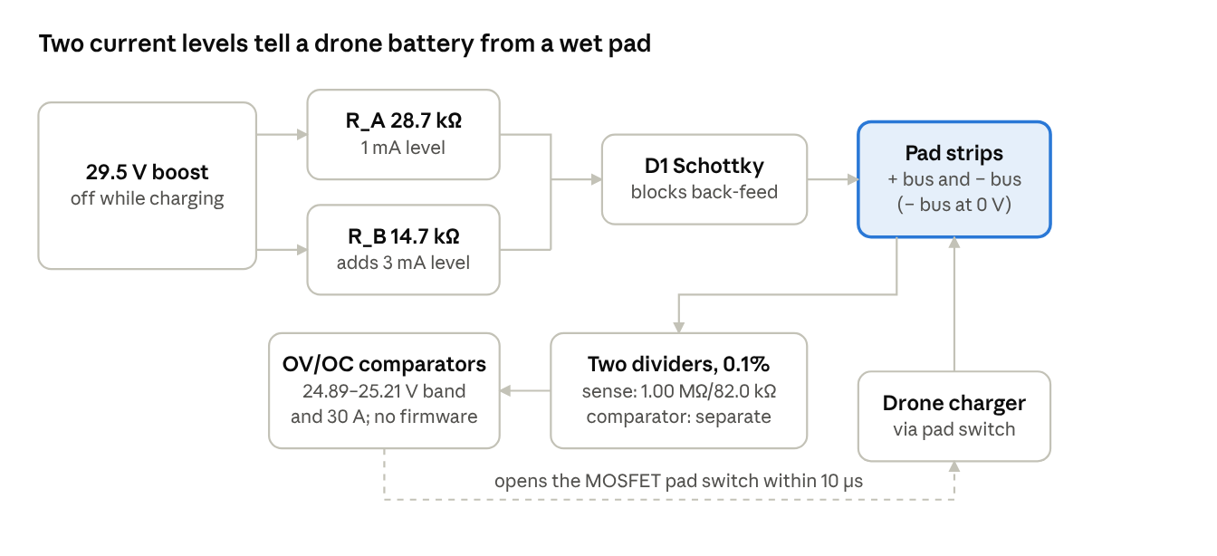
The controller runs the two-level check with the output switch open and the charger disabled. With Q1 off, the boost drives the pad through R_A alone (about 1 mA into a short); with Q1 on, R_B sits in parallel (9.72 kΩ, about 3 mA). The sense divider stays across the pad at all times. It is high-impedance (1.08 MΩ) and built from 0.1% parts, so an open pad reads at least 28.5 V, outside the window by itself. D1 keeps the charger's output out of the sense source during charging, when the boost is disabled. The boost must have a true output disconnect, because an ordinary boost converter passes its input straight through when disabled.
The hardware overvoltage comparator has its own divider (0.1%, 10 ppm/K) and reference (0.1%, 20 ppm/K). With comparator offset and drift over −20 to 60 °C, its trip band is 24.89–25.21 V around a 25.05 V nominal: at most 4.20 V per cell, and 0.17 V above the CV maximum of 24.72 V. With 1% parts the band would be 24.3–25.8 V, which fails both ways (simulation 6).
The comparators are latched, and firmware clears the latch only while the switch is off. The sense check puts up to 29.5 V on an empty pad, which sets the overvoltage latch harmlessly because the switch is off then; firmware clears it and confirms it stays clear before turning the switch on.
Revision 2 put the band at 25.30–25.50 V. That is 4.22–4.25 V per cell, above the cell limit, and the second review caught it.
| Part | Value | Tolerance and rating | Why |
|---|---|---|---|
| Boost source | 29.5 V, ≤50 mA, true output disconnect | ±1%; enable pin | Stays under 30 V at +1%; open pad reads above the window |
| R_A | 28.7 kΩ | 1%, 0.25 W | ~1 mA level |
| R_B | 14.7 kΩ | 1%, 0.25 W | R_A ‖ R_B = 9.72 kΩ, ~3 mA level |
| Q1 | Small-signal P-MOSFET | ≥60 V; gate clamped by a 12 V zener | Switches R_B in; gate-source limit is ±20 V on a 29.5 V rail |
| D1 | Schottky, BAT46-class | ≥100 V, ≥150 mA | Blocks back-feed while charging |
| Sense divider | 1.00 MΩ / 82.0 kΩ | 0.1% | 29.5 V to 2.2 V; high impedance |
| ADC path | Unity-gain buffer, 12-bit ADC, external 3.3 V reference | Reference 0.2% (ADC path only; the OV comparator has its own 0.1% reference); Monte Carlo allows ±0.5% gain | The 76 kΩ divider source needs a buffer |
| OV comparator | Own 0.1% / 10 ppm/K divider, 0.1% / 20 ppm/K reference; nominal 25.05 V; latched | Band 24.89–25.21 V over −20 to 60 °C | Opens the MOSFET switch with no firmware in the path |
| Pad output clamp | Bidirectional TVS (≥30 V standoff, ≤58 V clamp) and RC snubber | Sized for opening 80 A into lead inductance | Keeps the 60 V switch inside its rating when it opens |
| OC comparator | 30 A on a 1 mΩ shunt | ±1% | 1.5 × the largest setpoint |
| Output current sense | 1 mΩ shunt and current-sense amplifier | ±1% | Firmware overcurrent at 1.25 × setpoint, taper rule |
| Pad output switch | Back-to-back N-MOSFETs with a high-side driver | 60 V, 40 A continuous, 150 A interrupt | Simulation 6 peak was about 80 A for 10–20 µs |
The firmware constants come from the tolerance Monte Carlo (two runs of 600 builds at −20, 25 and 60 °C; 490,800 cases; no false accept or false reject). Every build drew both rectifier conduction modes (active ideal diode, or MOSFET body diode) [7]:
- Accept window: 17.6 to 27.6 V on the 3 mA reading. Pack readings span 17.93–26.87 V, and the open pad reads at least 28.5 V.
- Maximum change between levels: 0.30 V. Packs change by at most 0.12 V; films inside the window change by at least 2.0 V.
- Pre-charge: every charge starts with 10 s at C/10 and continues at C/10 until the pad voltage under charge exceeds 19.5 V. The decision uses the voltage under current, when the rectifier conducts actively, so the rectifier's offset at milliamp levels (up to 1.25 V in body-diode mode) cannot mislead it. A sense reading of 24.4 V or more ends the session without powering the pad and without a fault (pack already full).
Pad and contact layout
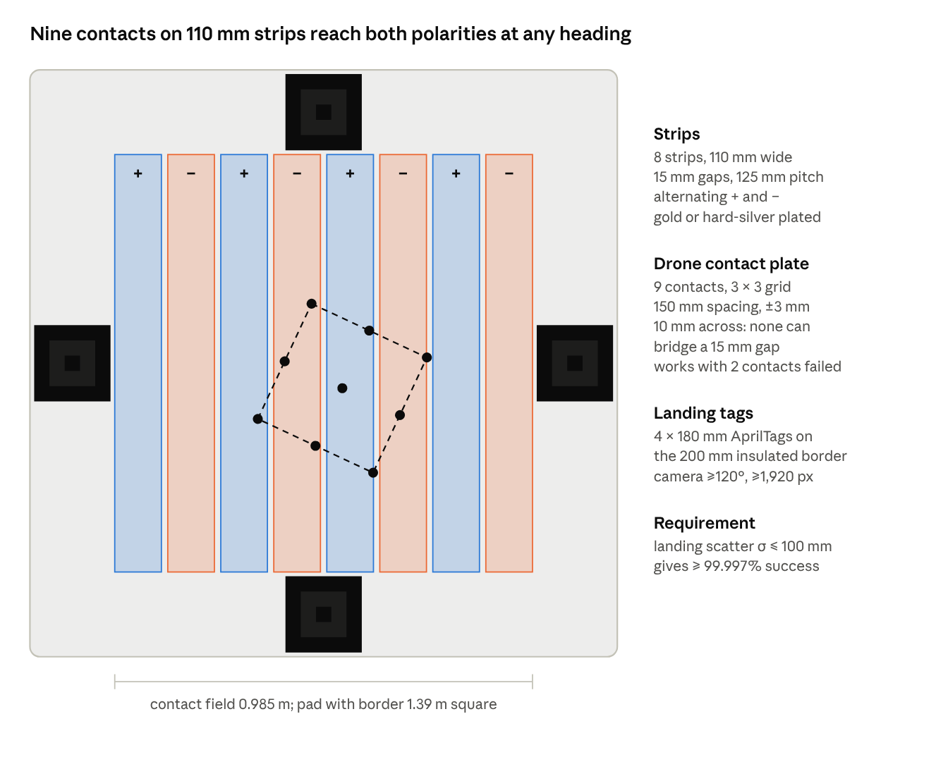
The contact field is eight alternating strips, 110 mm wide with 15 mm gaps, 0.985 m across [5]. The drone's contact plate has nine contacts on a 3 × 3 grid at 150 mm spacing. The four 180 mm AprilTags sit on a 200 mm insulated border, so the pad is 1.39 m square. The companion camera computes the pad centre from whichever tags are in view and sends that point as the MAVLink landing target. If a drone's contact grid is not 300 mm square, scale the strips by the rule in the drawing and re-run simulation 5.
Controller states
| State | Pad | Entry | Actions | Exit |
|---|---|---|---|---|
| IDLE | Unpowered | Power-up; drone gone | Every 2 s: two-level sense check; shaded ambient 0–45 °C | Check passes → START |
| START | Unpowered | Sense passed | Pad empty → IDLE. Sense reading ≥ 24.4 V → DONE (already full). Required energy = charge energy minus 80% of grid output over the charge if a grid kit is present; grid on if needed | Storage can finish and a fresh sense check passes → CHARGE; storage short, or interior above 43 °C → WAIT |
| WAIT | Unpowered | Storage short | Pad empty → IDLE; grid on if present; recheck every 60 s | Storage sufficient and a fresh sense check passes → CHARGE |
| CHARGE | Powered | Relay closed; converter pre-biased below pack; switch on; current ramped over 100 ms | 10 s at C/10, then C/10 until pad > 19.5 V under charge; then 10, 20 or 9 A (drone-type switch); CV 24.6 V; interior > 42 °C halves current, > 45 °C ends the charge; every 1 s, 20 ms pause and two-level re-check | Faults (count toward lockout): OV 25.05 V; OC 1.25 × setpoint; UV (< 15 V, or 2 V below the running maximum; blanked during ramps); re-check showing a parallel path; pad > 80 °C; hardware OV 24.89–25.21 V or OC 30 A. Ends without fault: taper C/20 + 0.3 A at CV; open pad on the re-check (drone left, or its BMS opened the pack); 3 h; ambient out of range; interior > 45 °C; storage at 20% with no grid current → DONE |
| DONE | Unpowered | Taper, full, environment, timer, reserve | Switch off, then relay open; log session | Empty pad → IDLE |
| FAULT | Unpowered, latched | Electrical fault | Log; no retry for that drone | Empty pad → IDLE; 3 electrical faults in 24 h → LOCKOUT |
| LOCKOUT | Unpowered | Repeated electrical faults | Status light; out of service | Reset on site |
Every transition and trip in this table is implemented in the reference controller (controller.py, revision 3) and exercised by the test suite [6], including turn-on from START, a drone leaving during WAIT, a bridge across the strips during a charge, and a full pack landing.
Configuration settings
| Setting | Value | Source |
|---|---|---|
| MPPT maximum charge current | 25 A | Simulation 3 |
| MPPT battery profile | LiFePO4, absorption 28.4–28.8 V per battery datasheet | Battery datasheet |
| Grid charger | LiFePO4 preset; Bluetooth permanently disabled | Victron manual |
| Grid on / off | Below 40% / at 80%; on for a waiting drone; forced on below 15% by hardware (takes precedence over the lockout) | Simulation 3; flat-battery recovery |
| Grid solar lockout | Grid off when solar current exceeds 13 A | 13 A + 12 A = 25 A |
| Grid energy credit | 80% of grid output over the charge | Simulation 3 |
| Drone CV | 24.6 V only | Simulations 2 and 6 |
| Drone current | Quad 10 A; VTOL 20 A; L1 9 A; 10 s C/10 probe; C/10 until pad > 19.5 V | Drone-type switch; simulation 6 |
| Turn-on | Converter pre-biased below pack; 100 ms current ramp; UV blanked during ramps | Simulation 6 |
| Already-full threshold | Sense reading ≥ 24.4 V: no charge, no fault | Simulation 6 |
| Interior start limit | No charge starts above 43 °C interior (WAIT until it cools) | Stress test |
| Charge end | C/20 + 0.3 A at CV, or 3 h; drone avionics ≤ 0.3 A while charging | Simulation 2 |
| Sense window / max change | 17.6–27.6 V / 0.30 V; re-check every 1 s (20 ms pause) during charge | Simulations 6 and 7 |
| Firmware trips | OV 25.05 V; OC 1.25 × setpoint; UV < 15 V or 2 V below running maximum; pad 80 °C | Simulation 6 |
| Hardware trips | OV 24.89–25.21 V (nominal 25.05 V); OC 30 A; latched; 10 µs | Simulation 6 |
| Lockout | 3 electrical faults in 24 h (environment, timer and reserve ends do not count) | Simulation 6 |
| Temperature | Shaded ambient 0–45 °C; drone cell NTC 0–45 °C (BMS); interior > 42 °C halves current, > 45 °C ends the charge | Simulation 8 |
| Load disconnect | 10% storage charge | Flat-battery recovery |
Sizing
The figures below are outputs of simulation 3: a one-minute energy balance run over 14 days for each configuration, with a drone always waiting. The assumptions are stated so they can be replaced with site data:
- Sun: half-sine sun scaled to 4 peak-sun hours over a 12-hour day (a mid-latitude annual average), or 1.5 peak-sun hours over 9 hours (winter).
- Losses: a 75% derate from panel nameplate to energy stored.
- Storage: 98% discharge efficiency; used between 20% and 100% charge (1.02 kWh usable).
- Idle draw: 2 W.
- Charge basis: each drone arrives empty and is charged to 25.2 V, which overstates a typical charge. That draws 251 Wh from storage for the quad pack (6S, 10 Ah, 222 Wh) and 557 Wh for the VTOL pack (6S, 22 Ah, 488 Wh), per simulation 2.
| Configuration | Quad charges per day (4 / 1.5 PSH) | VTOL charges per day (4 / 1.5 PSH) | From storage alone (no sun) |
|---|---|---|---|
| Large kit, 2 × 300 W | 6.8 / 2.5 | 3.1 / 1.1 | 4 quad or 1.8 VTOL |
| Small kit, 2 × 100 W | 2.2 / 0.7 | 1.0 / 0.3 | 4 quad or 1.8 VTOL |
| Grid kit, ~300 W | 16 (charge time limits) | 12.7, one per 1.9 h (grid power limits) | Not limited |
| Large kit + grid | 16 | 14 | Not limited |
Under 30 days of random cloud cover averaging 4 peak-sun hours, the large kit averaged 6.8 quad charges per day (worst day 2, best 9), and the small kit 2.1 (worst 1, best 3). Storage never fell below the 20% reserve except by idle draw while no charge was running.
Winter sun is the binding case. Peak-sun hours can fall to roughly 1 to 2 per day in December at northern U.S. latitudes, and the 1.5-PSH columns cut the solar rows by about 60%. Size a site that must serve a set number of flights in winter on its worst month, using NREL PVWatts for that location, or give it the large kit or a grid kit.
Spacing. This is a design rule, not a derived value. Pods sit no farther apart than about 70% of the drone's rated range, leaving a reserve for headwind, a missed landing, and a diversion to the next pod. A pod that is occupied or faulted is treated as absent; the drone diverts or falls back to charging from its own panels.
Parts list
The specification column is binding: a substitute part must meet every rating listed. Named products are examples that meet the specification, and none is required. Prices are single-unit estimates. Only the grid charger's price ($177.65, one U.S. retailer, November 2026) was checked against a listing; quote the rest before budgeting.
Universal pod (identical at every site)
| # | Part | Specification | Purpose | Approx. cost |
|---|---|---|---|---|
| 1 | Storage battery | LiFePO4 25.6 V 50 Ah; BMS ≥50 A continuous; charge ≥40 A (covers the 37 A cloud-edge transient and the hardware grid force-on); low-temp charge cutoff; charge path stays open in undervoltage cutoff; wired RS-485/CAN/UART; no Bluetooth; 6,000-cycle cells for grid sites | Stores 1.28 kWh for drone charging | $450–650 |
| 2 | Solar charge controller | Victron BlueSolar MPPT 150/35 (150 V, 35 A, 1,000 W at 24 V, VE.Direct, no Bluetooth); maximum charge current set to 25 A | Charges storage from either solar kit | $250–300 |
| 3 | Drone charger | Buck-boost CC/CV; 20–29.2 V in; ≥25 A continuous at 50 °C; CV accuracy ±0.5%; enable and current-set inputs; ≥93% efficient | Charges the drone pack | $100–250 |
| 4 | Controller | RP2040 or STM32 board, no radio hardware; SD card; three-position drone-type switch (quad 10 A, VTOL 20 A, L1 9 A); independent hardware watchdog (100 ms) that turns the pad switch off and opens the relay if firmware stops | Charge logic, sense check, logging | ~$30 |
| 5 | Relays (2) | Pad: back-to-back MOSFET switch (60 V, 40 A continuous, 150 A interrupt) plus a sealed isolation relay rated to break at least 150 A DC at 32 V (the backup if the switch fails closed); grid: latching DC relay behind an ideal diode. Not generic DC SSR modules | Switch grid input and pad output | $60–100 |
| 6 | Fuses | 50 A Class T or MRBF at battery; 15 A PV; 20 A grid; 30 A fast-acting pad output fuse; TVS and RC snubber across the pad switch output | Overcurrent protection | $70–90 |
| 7 | Landing pad | 1.39 m square overall: 0.985 m contact field plus a 200 mm insulated border carrying 4 × 180 mm AprilTags; rated for 2 kPa snow load; 8 alternating strips of gold- or hard-silver-plated copper or brass, 110 mm wide with 15 mm gaps; mounted on standoffs to shade the lid | Landing target, charge contacts, sun shade | $250–450 |
| 8 | Sense circuit | 29.5 V boost with output disconnect; R_A 28.7 kΩ and R_B 14.7 kΩ (1%); Schottky blocking diode; 1.00 MΩ / 82.0 kΩ divider (0.1%) and ADC buffer; OV comparator with its own 0.1% / 10 ppm/K divider and 0.1% / 20 ppm/K reference; 30 A OC comparator; 1 mΩ shunt (see Detailed design) | Confirms a drone before the pad is powered | ~$25 |
| 9 | Enclosure | IP65/IP67 rugged case, white, pressure-equalizing vent; through-wall aluminium heat-sink plate ≤0.25 K/W carrying the charger, solar controller and pad switch | Weather and impact protection | $260–400 |
| 10 | Weatherproof ports | MC4 bulkhead (solar); Anderson SB50 or IP68 circular (grid); capped service port | Kit connections without opening the case | ~$60 |
| 11 | Sensors | Shaded ambient, interior and pad (overheat alarm) temperature probes; lid tamper switch; DC surge protector at the PV port (Type 2, Ucpv ≥120 V) | Temperature limits, tamper log | ~$60 |
| 12 | Wiring | 6 AWG battery leads; 10 AWG PV and output; ring terminals; cable glands | Internal power wiring | ~$50 |
| 13 | Mounting | Adjustable legs; 4 auger ground anchors rated ≥1.5 kN each (covers 35 m/s wind with SF 1.5, even with all uplift on the windward pair); tie-down straps | Level and secure the pod | ~$120 |
| Pod subtotal | ~$1,800–2,600 |
Input kits (choose per site)
| Kit | Contents and binding specification | Approx. cost |
|---|---|---|
| Large solar | 2 × 300 W rigid panels, each Voc ≤40 V at STC (wired in series); ground or roof frame; 10 m PV cable with MC4 | $350–500 |
| Small solar | 2 × 100 W folding panels, each Vmp ≥20 V at STC (wired in series); stakes; 5 m PV cable with MC4 | $250–350 |
| Grid | Victron Blue Smart IP67 24/12 (120 VAC), Bluetooth permanently disabled; grid-port lead; plugs into a GFCI-protected outdoor outlet | ~$180–220 |
Drone-side kit (fitted once per drone)
| Part | Specification | Approx. cost |
|---|---|---|
| Contacts | Contact plate with 9 spring contacts on a 3 × 3 grid at 150 mm spacing, 10 mm diameter, gold plated, each rated ≥25 A continuous and 150 A for 20 ms, placed within ±3 mm | $20–40 |
| Ideal-diode rectifier | One ideal-diode pair per contact (9 pairs: high-side to the + rail, low-side from the − rail), MOSFETs ≥60 V, ≥25 A continuous, ≥150 A for 20 µs | $30–60 |
| Active balancer | 6S active cell balancer | $15–25 |
| Landing camera | Camera board with on-board AprilTag detection, or a companion computer with radios disabled; MAVLink LANDING_TARGET output | $65–90 |
Each drone pack also needs a per-cell BMS (see Contacts and drone detection), about $20–40 if the pack lacks one. The camera needs a horizontal field of view of at least 120° and at least 1,920 pixels across. The whole drone-side kit adds an estimated 0.30 kg. By simulation 10 that costs a 3 kg multirotor about 13% of its endurance and a 3 kg fixed-wing about 9% of its range, so pod spacing must use the reduced range. Weigh the kit on the chosen parts.
Deployment and operations
Siting
- Place pods along the planned route at no more than 70% of drone range apart.
- Choose a level spot with open sky above the pad (no wires or branches within about 5 m) and, for solar sites, a clear southern view (northern in the southern hemisphere) from mid-morning to mid-afternoon.
- Keep the pad at least 0.5 m off the ground where snow, standing water or tall grass is likely.
- Record each pod's coordinates and pad heading in the flight plan; the drone uses GPS to reach the pod and the AprilTag for the final landing.
Setup at a site
- Set the pod on its legs, level it, and fix it with four auger anchors rated at least 1.5 kN each. Wind uplift on the pad exceeds the pod's weight at about 18 m/s (40 mph). Anchor the large-kit frame, and stake folding panels at every corner or bring them in before storms. At fixed sites, bond the case and pad frame to an earth rod.
- Set the drone-type switch inside the case for the route's airframe: quad (10 A), VTOL (20 A) or L1 (9 A, both L1 aircraft). This is done once, at build or assignment.
- Fixed site: mount the large panels on a ground frame, or on a roof subject to the code notes below. Run PV cable to the MC4 port. Plug the grid kit into a GFCI-protected outdoor outlet and the grid port.
- Remote site: unfold the small panels beside the pod, angle them toward the sun, stake them, and connect them to the MC4 port.
- Open the case only to read the SD card or update firmware; normal setup does not open it.
- Confirm the status light: it shows storage charge and confirms the pad is unpowered.
- Run one test landing and charge before adding the pod to live routes.
Charge sequence
- The drone lands on the pad using the tag.
- The controller runs the sense check. If the two-level sense check fails, the pad stays unpowered and the drone lifts and lands again.
- The controller checks shaded ambient temperature (0 to 45 °C) and storage charge; the drone's BMS separately blocks charging if its cells are outside 0 to 45 °C. If storage cannot finish the charge, the pad stays unpowered. The drone then charges from its own panels or continues to the next pod.
- The output relay closes, then the MOSFET switch turns on. The charger ramps up over 100 ms, runs 10 s at C/10 and stays at C/10 until the pad voltage under charge exceeds 19.5 V, then runs constant current at the switch-selected rate, then constant voltage at 24.6 V, and stops when current tapers to C/20 + 0.3 A. Every second it pauses for 20 ms and repeats the two-level sense check; a failed check ends the charge as a fault.
- The MOSFET switch turns off, then the relay opens. The drone's flight controller opens its BMS charge FET before arming and departs on its schedule. The session is logged.
- The MOSFET switch opens at once on overvoltage (firmware 25.05 V; hardware 24.89–25.21 V), overcurrent, undervoltage, a failed re-check, or a pad above 80 °C.
Maintenance
- Every visit or monthly: clean the pad contacts and the AprilTag, wipe panels, check legs and straps, pull the SD log.
- Seasonally: check panel angle, clear vegetation, inspect seals and cable glands.
- Yearly: check storage capacity from the log, replace the drone-side contacts if worn.
- Any sustained fault in the log (failed charges, high case temperature, tamper events) means the pod is taken out of the route until inspected.
Moving a pod
Because pods are identical, relocating one means unplugging its kit, moving the case and plugging in the kit that fits the new site. Nothing in the pod needs to be reconfigured.
Safety, regulatory and open questions
Safety
- Electrical.
- The pad is unpowered unless the two-level sense check passes. The sense source is limited to about 3 mA at under 30 V.
- The pod never carries mains voltage.
- Every source and load is fused, and the battery fuse is rated to interrupt the pack's short-circuit current.
- The grid input has an ideal diode, so its port pins are dead when unplugged and reverse polarity cannot pass.
- The grid kit plugs only into a GFCI-protected outlet.
- Overcharge. Three independent layers protect the drone pack:
- the charger's CV setpoint, 24.6 V, which is at most 4.12 V per cell with tolerance;
- the overvoltage cutoff: a latched hardware comparator (24.89–25.21 V, at most 4.20 V per cell, opening a MOSFET switch in 10 µs) and firmware (25.05 V);
- the drone pack's per-cell BMS. This is the only layer that protects a wrong-cell-count pack or an unbalanced cell, which is why it is mandatory.
- Short circuits and failures. A pad short is caught by the undervoltage trip even when the converter's current limit works. A conductor bridging the strips while a drone charges is caught by the two-level re-check every second, with at most about 0.2 kJ delivered into it. A converter that loses regulation is cut by the hardware path within 1 ms at any drone state of charge (simulation 6).
- Thermal.
- LiFePO4 storage.
- A white, shaded case with the charger and pad switch on a through-wall heat sink.
- Drone charging gated by the drone BMS's cell NTC and the pod's shaded ambient sensor (0–45 °C), and derated above 42 °C interior.
- Storage charging limited by its BMS.
- The drone's lithium-ion pack is the higher fire risk; any voltage, current or temperature fault stops the charge.
- Physical. Four anchors rated at least 1.5 kN each hold the pod against wind uplift up to 35 m/s with a 1.5 safety factor, even if off-centre pressure puts all the uplift on the windward pair. The pad surface is non-slip, with rounded edges.
- Surge. A Type 2 DC surge protector at the PV port, bonded to the case. Fixed sites are bonded to an earth rod. The pod has no lightning protection against a direct strike.
- Unattended charging. A drone charging alone in a field is the main residual risk. The controls available without a radio link are the protection layers above, siting away from dry brush and structures, lockout after three faults in 24 hours, and logging every session.
Regulatory (United States)
- Flight rules.
- A pod network implies flights beyond visual line of sight. Under Part 107, that needs a waiver of 14 CFR 107.31 (visual line of sight), granted under 107.205.
- The FAA's proposed Part 108 BVLOS rule (90 FR 38212, August 7, 2025) would create a standing path. Its final rule has been under OIRA review since July 10, 2026, and as of late October 2026 no publication date had been announced.
- The drone needs Remote ID (14 CFR Part 89).
- Electrical code.
- Fixed-site solar falls under NEC Article 690 and local permitting. The string's cold-weather maximum voltage is calculated under 690.7.
- A roof-mounted array may bring in the rapid-shutdown requirements of 690.12; a ground mount avoids them.
- A plug-in grid kit on an existing GFCI outdoor outlet usually needs no permit, but local rules govern.
- Shipping.
- The storage battery (1.28 kWh) and both drone packs (222 Wh and 488 Wh) are lithium-ion batteries over 100 Wh. Each must be of a type tested under UN 38.3, with a test summary available, under 49 CFR 173.185(a).
- Each falls outside the small-battery exception in 173.185(c) and ships as Class 9 hazardous material.
- Land access. Each pod needs the landowner's written permission. Public land generally needs a permit.
- Radio-frequency emissions. The pod contains switching converters and a microcontroller, so it is an unintentional radiator under 47 CFR Part 15 Subpart B. A marketed product needs Class A or B verification. A builder's own units fall under the home-built provision (47 CFR 15.23: no more than five, not marketed) but must not cause harmful interference. Mitigations: the metal heat-sink plate as a ground plane, short switching loops, and ferrites on the PV and pad leads.
Open questions
- Contact reliability. Wear and corrosion of plated strips and spring contacts over months outdoors. Needs bench mate/unmate cycling, salt-fog exposure and a season in the field, tracking contact resistance against the 5 mΩ assumption.
- Contact geometry on hardware. Landing tests to confirm the simulated result: one contact on each polarity at every heading, no bridge, and tolerance to two failed contacts.
- Landing accuracy. Landing scatter for this airframe in wind, rain and low light must be within σ = 100 mm, including the last 0.4 m flown on the held estimate. An illuminated or retroreflective tag may be needed.
- Drone mass and range. The estimated 0.30 kg drone-side kit costs about 9–13% of range on a 3 kg airframe (simulation 10). Weigh it, then re-space pods.
- Thermal performance. The steady-state model needs a sun test of the built case: interior, heat-sink and pad temperatures at full charge load.
- Snow, ice and debris. Snow covers the contacts, and the pad must carry 1.9–3.8 kN of snow load. Decide whether cold sites need a sloped or heated pad.
- Start-up into a flat battery. Confirm on the bench that the chosen solar controller and grid charger start into a pack whose BMS is in undervoltage cutoff.
- Charger and BMS interaction. Confirm on real packs that the drone BMS's charge FET, balancer and avionics draw behave as modelled during a full charge, including taper termination.
- Theft and tampering. At remote sites, the no-radio design can log these but not prevent them.
- Prior art. The search so far finds:
- US 11,728,663 B2 (priority 2018, active). Its claim 1 covers a solar-powered station with storage, a landing platform, and sensing of the drone before energy is transferred, by inductive charging. This pod charges through conductive contacts, which claim 1 does not recite. That distinction needs review by a patent attorney before any claim of freedom to operate.
- Florczak et al. (2025). Solar-powered stationary and portable docking stations for quadrotors, operated as a networked system.
- DJI Dock 2. Requires an internet connection (Ethernet or 4G) for setup and operation.
Solar power, off-grid operation and drone sensing before charging are therefore not new on their own. What remains distinguishing is the combination: no radio hardware, a polarity-independent multi-contact conductive pad, and one identical pod with plug-in power kits. Novelty of that combination needs a full patent search.
References
- Victron Energy, SmartSolar MPPT 100/30 & 100/50 manual, §9 Technical specifications (Vbat + 5 V start, Vbat + 1 V run). https://www.victronenergy.com/media/pg/Manual_SmartSolar_MPPT_100-30__100-50/en/technical-specifications.html
- Victron Energy, MPPT 150/35 datasheet (35 A; 1,000 W at 24 V; 150 V absolute maximum, 145 V start/operate; −30 to +60 °C, full output to 40 °C; 15 mA at 24 V). https://www.upwatt.com/mpattachment/file/download/id/59
- Victron Energy, Blue Smart IP67 Charger manual, §6.2.3 Disabling Bluetooth, Option #2 (permanent and irreversible). https://www.victronenergy.com/media/pg/Blue_Smart_IP67_Charger_230V_manual/en/setup---bsc---psc.html
- Northern Arizona Wind & Sun, listing for Victron Blue Smart IP67 24/12, 120 VAC (100–135 VAC input, 12 A, $177.65). https://www.solar-electric.com/victron-energy-blue-smart-ip67-24-12-120-vac-battery-charger.html
- ArduPilot, Precision Landing and Loiter (MAVLink LANDING_TARGET, AprilTag via companion computer, “centimeter-level”). https://ardupilot.org/copter/docs/precision-landing-and-loiter.html
- Analog Devices, LT4320 Ideal Diode Bridge Controllers (9–72 V, DC to 600 Hz, polarity-agnostic input). Revision 1 component, superseded by one ideal-diode pair per contact. https://www.mouser.in/new/analog-devices/adi-lt4320-controllers/
- 49 CFR 173.185, Lithium cells and batteries. https://www.law.cornell.edu/cfr/text/49/173.185
- FAA, Normalizing Unmanned Aircraft Systems Beyond Visual Line of Sight Operations (NPRM), 90 FR 38212 (Aug. 7, 2025). Status: DroneBundle, Part 108 NPRM: Status, Timeline and What Happens Next (Oct. 7, 2026), https://dronebundle.com/blog/part-108-nprm; DroneRanker, FAA Part 108 BVLOS Rule Status (updated Oct. 21, 2026), https://www.droneranker.com/faa-part-108-bvlos-rule-status/
- US 11,728,663 B2, Drone recharging station (priority July 24, 2018). https://patents.google.com/patent/US11728663
- D. Florczak, M. Jacewicz, A. Kopyt and R. Głębocki, Autonomous solar-powered docking station for quadrotor drones: design and testing, SAGE (2025), doi:10.1177/09544100251331282.
- RTKdata, DJI Dock 2 integration (internet via Ethernet or 4G required). https://docs.rtkdata.com/integration-hub/drones-and-uavs/dji-dock-2
- NFPA 70, National Electrical Code, Article 690 (690.7 maximum voltage; 690.12 rapid shutdown).
- Victron Energy, SmartSolar MPPT 150/35 & 150/45 manual, Technical specifications. https://www.victronenergy.com/media/pg/Manual_SmartSolar_MPPT_150-35__150-45/en/technical-specifications.html
- 47 CFR Part 15, Subpart B (unintentional radiators) and §15.23 (home-built devices).
- ASCE/SEI 7, Minimum Design Loads, free-roof net pressure coefficients (basis for the CN = 1.2 assumption in the wind analysis); NEC 690.7 temperature correction.
Charging Pod · L1 aircraft results · On-board solar · Verification · Sanctir L1